• Skip to primary navigation
  • Skip to main content
  • Skip to footer
AddUp

AddUp

  • Machines
    • Machines
      • PBF
        • FormUp 350
        • FormUp 350 Evolution
      • DED
        • Modulo 400
        • Magic 800
      • Software
        • AddUp Dashboards
      • Why AddUp
        • Customer Journey
        • Certifications
  • Service
    • Service
      • Consulting
      • Training
      • AddUp Academy
  • Industries
    • Industries
      • Medical
      • Tooling & Molding
      • Aerospace & Defense
      • Other
  • Applications
  • Resources
    • Resources
      • Guide to Metal 3D Printing
      • Blog
      • Videos
      • Events
      • Materials
      • Downloads
      • AddUp Academy
      • Customer Portal
  • Company
    • Company
      • News & Press
      • Partners
      • Careers
      • Company Locations
      • Supplier Portal
  • Contact
        • Search

  • EN
    • FR
    • DE

PBF

September 29, 2023 by

INDUSTRY

Aerospace

CHALLENGE

Reducing the mass and lead time while optimizing
an Aircraft Floor Bracket

KEY BENEFITS
  • 61% mass reduction of the part
  • Part printed without any supports
  • Industry leading surface finish
icon addup
Reduced Lead Time
icon addup
No Support
icon addup
Weight Reduction

This proof of concept demonstrated by Add Up showcases the value of using Additive Manufacturing (AM) for aeronautics by applying topological optimization to an aircraft floor bracket.

History

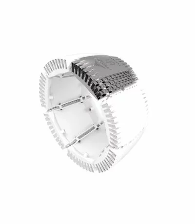
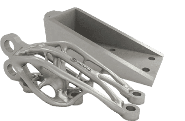
An aircraft floor bracket secures the cabin floor to the fuselage and is present in large quantities in all aircraft. AddUp developed this proof of concept demonstrator to illustrate the value of using Additive Manufacturing for aeronautics by carrying out a topological optimization study with no supports. This part traditionally weighs around 3 kg and is typically machined from a 12 kg metal block.

Challenges

The weight of an aircraft poses various challenges, including structural integrity, fuel efficiency, payload capacity, and performance during takeoff and landing. Excessive weight can strain the aircraft’s structure, increase fuel consumption, limit payload capacity, and require longer runways.

Safety considerations, such as balance and stability, are crucial, and the cost and economics of weight must also be considered. To address these challenges, aircraft designers and operators focus on using lightweight materials, efficient designs, and operational practices that strike a balance between weight reduction, performance, and safety.

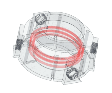
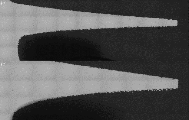
In most metal 3D printing machines, supports must be added to the part to produce surfaces with an inclination of less than 45° from the horizontal. These supports represent a significant cost and contribute to the time of part delivery.
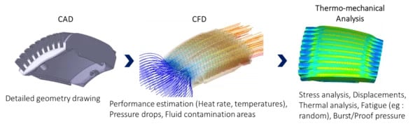
SOLUTIONS

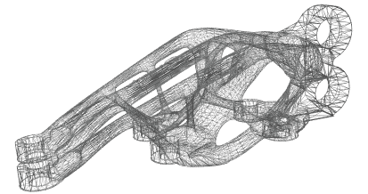
Topology optimization, the mathematical method that optimizes material within a given space with the goal of maximizing performance, was utilized to remove significant amounts of material.

First, a CAD model was created, incorporating the desired shape and the stress constraints the part needs to withstand.

Next, topological optimization algorithms evaluated the stress distribution throughout the part and systematically removed excess material from low-stress regions while reinforcing high-stress areas.

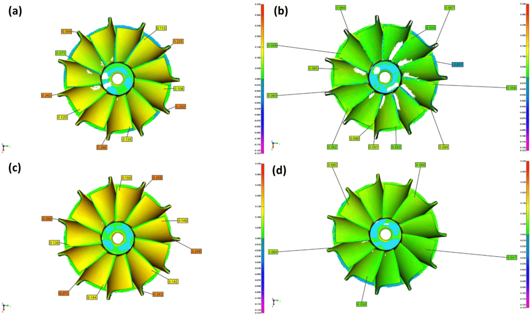
This resulted in a lightweight design that maintains structural integrity under anticipated loads. The part was then printed on the FormUp 350 powder bed fusion machine, using a fine powder and roller combo to reduce the need for supports. This combination also provided a smooth and uniform surface finish, which plays a critical role in the fatigue behavior LPBF parts and reduces the need for post-processing.

The Results

By utilizing the fine powder and roller recoater combination found only on the FormUp 350, there were no support structures required; overhangs can go as low as 30° or even 15°. By removing the need for support structures, 250 g of raw material was saved. This reduced the build time by 3 hours and saved another 30 minutes for support removal. This also lowers the overall total lead time, an important metric in the Aerospace industry.

Build Time on the FormUp 350 (at 50 μm)
11.50 Hours

Weight Reduction
From 3 Kg down to 1.17 Kg
A 61% weight reduction!

Raw Material Savings
10.83kg

Saved Time
3+ hours

September 29, 2023 by

INDUSTRY

Medical

CHALLENGE

As the world around us becomes more personalized, medicine is no different. To keep up, off the shelf solutions will become obsolete and personalized solutions will become the norm. How will the industry handle this customized changed from a manufacturing standpoint?

KEY BENEFITS
  • a net savings of US$736 per operation when using additively manufactured PSI (1)
  • a decrease in blood loss (of 44.72 mL) when using additively manufactured PSI (2)
  • a decrease in hospital stay (0.39-day decrease) (2)
icon addup
Custom Shape
icon addup
Performance
icon addup
Integrated Features

This case study highlights the advantages of using additive manufacturing (AM) for Patient Specific Implants (PSI) in the orthopedic industry. By shifting from traditional manufacturing to AM, orthopedic OEMs can meet the demand for personalized medicine and tailored solutions for patients.

History

Before the invention of industrial 3D Printing, all standard-line and even some Patient Specific Implants (PSI) were traditionally manufactured. Typically, this included manufacturing methods like casting and forging and CNC machining out of bar stock. These implants must be machined from a single piece of material (most likely titanium or stainless steel). This is a particularly expensive and technically sophisticated process. This leads to the PSI being costly and with an increased lead time.

When using AM, there are many ways that these devices can be cleared through the FDA. The easiest and most used is a 510k. This verifies a “build envelope” and ensure the PSI is functionally equivalent or better that the standard line implant. Another option is a Custom Device Exemption. This is an option that limits the manufacturing of a particular device type to 5 units per year(3). Humanitarian Use Devices (HUD) are medical devices intended to benefit patients in the treatment or diagnosis of a disease or condition that affects or is manifested in not more than 8,000 individuals in the United States per year. A Humanitarian Device Exemption (HDE) is a subset of the HUD. This type of PSI is exempt from the effectiveness requirements of Sections 514 and 515 of the FD&C Act and is subject to certain profit and use restrictions(4). These are the plethora of ways that OEMs and Manufacturers can help get the PSI into the hands of the surgeon.

Challenges

Orthopedic OEMs have been manufacturing standard line implants for mostly the same way since the 1970s. A shift to additively manufactured PSIs will change how surgeons treat their patients and will change the industry as we know it.

Conventional manufacturing, whether it be subtractive or casting and forging, is not inherently designed to make customized solutions. Therefore, the largest challenge will be convincing the OEMs and implant manufactures to change their manufacturing processes to match what the market is demanding. The market is demanding personalized medicine, and this will come in the form of PSI in the orthopedic industry.

The patients will need to work with surgeons to ensure that they receive the most tailored solution to their condition. This will also require cooperation from the hospitals and insurance companies to provide support for this industrial change. PSI can be cheaper and more beneficial to the patient, but as the technological shift occurs, PSI will most likely be more expensive. It will be up to the user, patient and surgeon, to vote with their wallet and the equipment they use to enable this technology to flourish.

SOLUTIONS

AddUp is uniquely equipped to help the industry shift from standard line implants to patient specific implants.

The FormUp 350 is built for serial production from the ground up. It can handle varying different complex geometries from fine detailed lattice that promotes osteointegration to a large semipelvis. These types of cases can all be built on a single build allowing for greater efficiency and throughput.

The modular build plate helps the manufacturer to adapt to surgical cases of any size and shape. This allows for greater efficiencies from each build. Efficiency will be key to the shift from standard product line to patient specific implants happening. As the population ages and a larger number of people live longer, there will be more and more surgeries. If medicine continues down the path of personalization, the FormUp 350 will be there to meet the demand of serial production of patient specific implants.

Lot traceability is inherently enhanced, and implants can get on to their next process faster without the need to wait on the remainder of the build. This means that each surgical case can go its own way closer to the beginning of the supply chain. A wider range of surgical implants can be produced on the same build since each implant is not subject to as many of the same processes. These further decreases lead times as PSI are especially sensitive to the amount of time between the CT scan to the surgery. Any amount of time between CT scan to surgery allows the bone’s anatomy to change as the patient continues living their day-to-day life. The less amount of time from scan to surgery, the better possible outcome for the patient; giving surgeon’s confidence that they have the correct tools for the job to best improve the patient’s life.

The Results

Using a Total Knee Arthroplasty (TKA) example, using a PSI manufactured via AM results in a net savings of $736 when compared to traditionally manufactured implants, thanks to a shorter operating time and fewer instrument trays required.(1) Patients and hospitals also reap the benefit of shorter operating room times, reduced by 20.4 min(1) when compared to traditionally manufactured implants.

It’s also been proven that a significant difference in blood loss occurs (decreased by 44.72 mL)(2) Lastly, a decreased hospital stay (0.39 day decrease) provides a significant benefit to both the hospital system and the patient. (2)

Using additively manufactured PSIs such as knee femoral and tibial components or acetabular hip cups, provide improved accuracy of biomechanical implant alignment(1), resulting in improved patient care and better patient outcomes.

References

1. Haglin, J.M., Eltorai, A.E.M., Gil, J.A., Marcaccio, S.E., Botero-Hincapie, J. and Daniels, A.H. (2016), Patient Specific Orthopaedic Implants. Orthop Surg, 8: 417- 424. https://doi.org/10.1111/os.12282

2. Schwarzkopf, Ran, et al. “Surgical and functional outcomes in patients undergoing total knee replacement with patient-specific implants compared with “off-the-shelf” implants.” Orthopaedic journal of sports medicine
3.7 (2015): 2325967115590379

3. https://www.fda.gov/regulatory-information/search-fda-guidance-documents/custom-device-exemption

4. https://www.fda.gov/medical-devices/premarket-submissions-selecting-and-preparing-correct-submission/humanitarian-device-exemption

Learn more about 3D Metal Printing for Custom Medical Implants:

September 29, 2023 by

INDUSTRY

Tooling & Molding

CHALLENGE

Increase the longevity and performance of an extrusion die while increasing the flexibility to produce dies of various sizes when additively manufactured.

KEY BENEFITS
  • Die extrusion rate for end-use product increased by 25%
  • Maximum temperature is 20°C lower on the new die due to conformal cooling
  • 6x Wear Performance: 12 weeks > 2 weeks (a 10-week improvement)
icon addup
Conformal Cooling
icon addup
Increased Productivity
icon addup
Increased Lifespan

This study explores the use of additive manufacturing, specifically Powder Bed Fusion (PBF), to create extrusion dies with improved performance and cooling capabilities.

History

Extrusion is a popular manufacturing method for parts with a constant profile. A couple examples from the world of plastics are PVC pipe and wiper blades, but metals and composites can be extruded as well. The material feedstock is forced through the profile of the die to transform it into the shape of the final part. In plastics extrusion, it is commonplace to machine the extrusion die out of aluminum. . Due to the design constraints of traditional machining, the extrusion die is often larger and bulkier than necessary, and lacks any sort of advanced cooling channels.

The simple geometry causes poor cooling performance, as the coolant cannot run near the inner profile of the die, making it way less efficient. It is also costly and time consuming to create different programs, jigs, and fixtures for different sized parts. Creating extrusion dies in specialty sizes would be too costly without the flexibility provided by additive manufacturing.

Challenges

Traditional manufacturing of extrusion dies is limited to materials that easy to machine. This material restriction conflicts with attempts to optimize performance of the die, especially when it comes to wear properties and tool life. The challenge is to utilize additive manufacturing (AM) to create a die made from a material that improves its durability and increases how long it lasts in production. The die must also utilize conformal cooling to improve thermal performance. Lastly, the overall cost of manufacturing the die must be decreased to allow for design changes to be implemented across a variety of manufacturing lines and machines.

SOLUTIONS

Powder Bed Fusion can print any 2D profile, which allows for a perfect match of any shape that may be extruded. Because PBF does not need any setup tooling, there is much more freedom with different quantities and differently shaped parts, perfect for specialty sizes and new extrusion dies without any additional investment. Extrusion dies can also be made from fewer parts, reducing spare parts burden and simplifying the manufacturing process.

Another added benefit from the geometric capabilities of AM is conformal cooling. Intricate cooling channels, which are impossible to machine, are implemented onto the contour of the part during printing. The optimal design of these channels allows for uniform temperature control leading to improved cooling and performance. Furthermore, the part is printed in Inconel 718, which is a nickel based alloy with high wear and corrosion resistance that can operate in high temperatures.

The Results

The new extrusion die created through AM stayed of 20°C cooler than a die made using traditional manufacturing methods due to the improved conformal cooling design. The lower temperature allowed for the product to be extruded through the die 25% faster, meaning a huge productivity boost without sacrificing any quality. Thermally, there is room to increase the extrusion speed, but other equipment on the line is now the bottleneck instead of the die itself. The new die also lasted six times longer than the previous one at 12 weeks rather than 2 weeks, even while operating at the increased speed.

Powder Bed Fusion has proven to be a valuable tool, poised to support the extrusion industry for a large number of potential applications.

chart addup

September 29, 2023 by

INDUSTRY

Automotive

CHALLENGE

Decrease production time and cost while improving performance when compared to traditional manufacturing by optimizing scan strategy.

KEY BENEFITS
  • Optimized scan strategy for better surface finish for Impeller geometries
  • Proved PBF as a viable option for Impeller’s in the automotive industry in terms of both cost and performance
  • Compared test and inspection methods for geometric and density uniformity of additive versus traditional parts
icon addup
Increased Productivity

This case study explores the feasibility of using additive manufacturing, specifically the Form Up 350 PBF machine, to produce over 100,000 Impeller wheels annually for Ford, replacing traditional machining techniques.

History

Ford uses traditional methods to manufacture over 100,000 Impeller wheels per year. Ford, Oak Ridge National Labs, and AddUp conducted a study to determine the feasibility of producing the impeller wheels through additive manufacturing using the FormUp 350.

Ford would leverage their extensive history of over a century of automotive experience. Oak Ridge National Labs would optimize the scan strategy and the DOE of contour passes. AddUp brings the expertise in design, manufacturing, and automation for large scale production using their industrial FormUp 350 PBF machine.

Challenges

Ford currently manufactures by utilizing traditional machining techniques to create their impeller wheels. The challenge proposed to AddUp was to investigate the performance of PBF technology as a replacement to mass manufacture these parts. The goal was to decrease production time and cost while improving performance when compared to traditional manufacturing. Thus, a single contour pass is sufficient given a position beyond the hatch lines to remove hatch patterning. Tolerances were also sufficient from the printer.

The result should be to effectively create 100,000 Impellers through additive manufacturing and create an optimal printing strategy for performance, leveraging the design freedom from AM while optimizing the scanning strategy for surface finish and productivity.

SOLUTIONS

The original test part was made from maraging steel to test the feasibility of geometries which resulted in demonstrating the viability of additively manufacturing a complete turbo wheel without the need for supporting low-angled features. The surface finish still had to be optimized and geometric tolerances in the as-printed conditions as close to the CAD model as possible. L-PBF often uses a contour followed by infill melt strategy to obtain parts with superior surface finish. If an insufficient overlap is used between the contour and infill, it can result in porosity at the contour-infill interface thereby making the part susceptible to premature failure. The part was tested with 1 contour pass and 5 contour passes. When melting with 5 contour passes, the surface had increased porosity compared to a single pass.

The Results

With the need for a rugged, heat resistant material, Inconel 718 was chosen. When printed with Inconel 718, a support structure on the bottom of the wheel was required. AddUp printed a simulation test build of 9 impeller wheels using Inconel 718. Following post processing, two wheels were selected to be balance tested.

chart addup
  • (a) Optical micrograph of single contour pass downskin

    (b) Optical micrograph of downskin using five contour passes. Although more contour passes may be useful, the position of the outermost contour drives surface finish as shown by partially melted particles clinging to the surface in.


Geometric tolerances measured from light-scanning of turbo wheels with the outer contour extending the following distance beyond CAD boundary:

  • (a) #08 at 36µm
  • (b) #11 at 11µm
  • (c) #13 at 61µm and
  • (d) #19 at 36µm but melted outer to inner.
PART NAMEIMPELLER
3D printer make and modelAddUp FormUp 350
Build Plate size350 x 350 mm2
Number of parts per batch25
Print time per batch32.28 hours
Material Cost estimate for Inconel 718$70/kg
Mass of part0.311 kg
Mass of support material0.05 kg
Depowder time per batch0.5 hours
Support Removal time per batch30 hours
Post processing time per batch (heat treatment)12 hours
Annual volume required100,000 units a year

August 11, 2023 by

This innovative design is tailored for curved surfaces and has demonstrated exceptional thermal performance. The entire heat exchanger was produced in a single manufacturing process, showcasing the efficiency and capability of AddUp’s approach.

For thermal equipment, additive manufacturing has a huge advantage. It allows the development of complex channel shapes, improving thermal performance and reducing volume. It also allows the manufacturing of shapes that are impossible to produce traditionally for this type of equipment (e.g. double-curved channels).

INDUSTRY

Aeronautics

CHALLENGE

3D print a heat exchanger with innovative design

KEY BENEFITS
  • Modular heat exchanger concept
  • A double-curved heat exchanger
  • Part printed in one go with thin walls
  • When damaged, replacement of the unit instead of the whole arrangement
icon addup
Custom Shape
icon addup
Assembly
icon addup
Thin Walls
icon addup
Performance

History

A heat exchanger is a system used to transfer heat between a source and a working fluid. Heat exchangers are used in both cooling and heating processes. Depending on the application, the fluids may be separated to prevent mixing or they could also be in direct contact. In the aeronautics industry, aircraft heat exchangers are used to take heat from the engine’s oil system to heat cold fuel. This improves fuel efficiency and also reduces the possibility of water becoming entrapped in the fuel, which could cause freezing.

Heat Exchanger With Additive Manufacturing or HEWAM is a project aiming to develop a heat exchanger using all the potential of additive manufacturing in a geometry that fits with a wide range of surfaces and volumes used in the aerospace industry. This project was developed by PrintSky and Temisth. PrintSky is a joint-venture between the AddUp group, an expert in metal additive manufacturing, and SOGECLAIR, one of the international leaders in the integration of high-value-added solutions in the fields of aeronautics, space, civil and military transport. Temisth is a company specializing in the development of customized thermal solutions using additive manufacturing.

PrintSky was in charge of the design aspect of the project, developing its own methodology to determine the characteristics of the metal part, in terms of mechanical, thermal, and manufacturability.

The production was then passed to the AddUp experts who 3D printed this aeronautical part on their FormUp® 350 machine. The goal was to produce a compact heat exchanger according to the PBF (Laser Powder Bed Fusion) process with an innovative shape and above all as efficient as “traditionally“ manufactured heat exchangers. And then, after the production, HEWAM was tested on a customized test loop developed by Temisth.

Challenges

The objective for HEWAM was to cool a liquid as oil entering the heat exchanger at 110°C with ambient air at -50°C. The mass flow rate of the oil is fixed. Air mass flow rate is given by the dynamic pressure of the air flow arriving in the area of the heat exchanger and the pressure drop characteristics of the device. The objective was to remove 2200W of the oil circulation (32g/s ~2,4 L/min) on one modulus of the heat exchanger by ensuring enough air flow through it. The main physical issue on this heat exchanger was to ensure enough airflow inside the heat exchanger with high heat transfer coefficient.

SOLUTIONS

The groups developed a specific methodology in order to ensure the thermal requirements with mechanical constraints and additive manufacturing feasibility for HEWAM. A specific design was created taking into account the variation of air temperature (from -50°C up to +25°C) and thus its density. The channel width was increased to limit air acceleration and pressure drop. In order to maintain thermal performances, the fins have an adaptative geometry along the air flow in order to consider air velocity and channel size changes. The physical design of the part was created to fit a wide range of surfaces and volume used in the aerospace industry. It was designed to include a double shape curve which allows this part to fit the curvature of aircraft engines.

HEWAM was printed twice, using two different materials. First, Inconel 718. This material is heavier than aluminum by more than 3 times and is less conductive, however for additive manufacturing, it presents more interesting characteristics. With Inconel, thin walls (<0.5mm) and fins (0.15mm) are possible without leakage. Designing the heat exchanger with these thin features allows for similar performance and weigh characteristics which are possible with aluminum.

A final advantage of this 3D printed part is the possibility of updating the exchanger with no need to develop a new tooling.

Results

The final result is a double-curved heat exchanger, suitable for curved surfaces with very successful thermal performance and printed in one go. A modular solution: exchangers can be arranged next to each other in order to deliver high exchange power. The curved shape is suitable for installation in aircrafts engine pylons. The testing validated the leakage (or tightness) of the part as well as its performance, both of which were very successful especially when compared with more conventional means of manufacturing.

chart addup
  • The testing validated the leakage (or tightness) of the part as well as its performance, both of which were very successful especially when compared with more conventional means of manufacturing.

  • For thermal equipment, AM has a huge advantage. It allows the development of complex channel shapes, improving thermal performance and reducing volume.

  • The AM process also offers the ability to manufacture shapes that are impossible to produce traditionally for this type of equipment (e.g. double-curved channels).

  • In addition, additive manufacturing technology also allows the Manufacture of a part from a single block, in one go. This avoids any other manipulation of the part that could alter it, such as assembly or machining. No welding either, which means no risk of fluid leakage in this new heat exchanger.

  • Lastly, because AM offers the ability to print in one piece, only the functional areas of the metal part are printed (fluid flow surfaces and fastening surfaces), resulting in significant material savings.

Read more about this part on the Temsith website

Temsith Site

August 11, 2023 by

See how to improve the cooling of the inserts on a mold using additive technology while increasing the mold’s performance and decreasing the cycle time.

Short injection times are crucial for profitability in the mold industry, especially in the case of injection molds. Zahoransky AG, a German manufacturer of injection molds, needed a mold insert with eight bores with mold rings. Read the case study about a joint project of Zahoransky and AddUp on how to improve the cooling of the inserts on a mold using additive technology while increasing the mold’s performance and decreasing the cycle time.

INDUSTRY

Tooling

CHALLENGE

To improve the cooling of the inserts on a mold using AM technology while increasing the performance of the mold and decreasing the cycle time.

KEY BENEFITS
  • Ready to use mold after heat treatment
  • Near contour cooling in the insert
  • Reduction of time & cost production
icon addup
Creative Shape
icon addup
Function Integration
icon addup
Lead Time
icon addup
Performance

History

In the mold industry, and especially in the case of injection molds, short injection times are crucial for profitability. They decide how many injection molding machines and molds you need and how high the final price of the part will be. The cooling system in the contour core insert has the most significant influence on these times. Today, the cooling channels are often still produced conventionally by drilling in 2D and cannot always run close to the contour and thus cool evenly and quickly.

Zahoransky AG, headquartered in Todtnau-Geschwend, Baden-Württemberg/Germany, is a manufacturer of injection molds, blister packaging machines, and production equipment. Zahoransky is the world market leader in mold and tool-making for the toothbrush industry. Around 80 percent of the world’s toothbrush molds come from Zahoransky.

Challenges

Zahoransky needed a mold insert with eight bores with mold rings. Up to now, these have had to be well cooled and elaborately sealed using O-rings. The challenge was to improve the cooling of the inserts using additive manufacturing technology in such a way that the cycle times and productivity of the molds would be significantly increased. The complex assembly of the O-rings was to be eliminated, thus reducing manufacturing costs.

The quality of the parts was to be maintained in the usual form. And in addition, the molds needed to be constructed with a steel material qualified for injection molding and had the corrosion and wear resistance for this production.

SOLUTIONS

AddUp optimized the cooling channels and designed them as closely as possible to the original contours using AM 3D options, including unique AddUp Manager adaptive strategies skills. All channels needed the same length and cooling capacity to ensure uniform cooling. AddUp utilized simulation software and thermal design optimization to ensure accurate and uniform cooling for this mold.

Next, the new mold was printed on AddUp’s PBF machine (Laser Powder Bed Fusion), the FormUp ® 350 New Generation, using a productive AM build-up strategy with four lasers. This mold was printed in just 30 hours.

Results

AddUp significantly reduced the production time for this mold when compared to traditional manufacturing time. Post-processing for this mold was also significantly reduced thanks to the roller technology offered on the AddUp FormUp 350.

AddUp’s unique combination of fine powder and a roller re-coater provides a superior surface finish, significantly reducing the time needed for post-processing. The mold was printed using a steel material 1.2709/Margin300. This material is a qualified tool steel offering good tool life in the mold.

Zahoransky was pleased with the quality of the mold as well as the production time.

The next step in this project is for another prototype to be manufactured with additional optimizations and in a newly developed tool steel 1.2083/PM420. This new material is a qualified injection molding steel widely used and offers good corrosion and wear resistance.

For more information about additive manufacturing technology for the tooling and molding industry, please do not hesitate to contact us.

Tooling for the manufacture of pipette tips, with a double quick-change system. Each heating element can be removed individually in no time
CAD: complex channels inside the part
  • « Go to Previous Page
  • Page 1
  • Page 2
  • Page 3
  • Page 4
  • Page 5
  • Go to Next Page »
AddUp SAS

13-33 Rue Verte
ZI de Ladoux, 63118 Cébazat
France

+33 (0)4 73 15 25 00
AddUp Inc

5101 Creek Rd,
Cincinnati, OH 45242
USA

+1 (513) 745-4510
AddUp GmbH

Campus-Boulevard 30
52074 Aachen
Germany

+49 241 4759 8581

Footer

  • Machines
    • PBF
      • FormUp 350
      • FormUp 350 Evolution
    • DED
      • Modulo 400
      • Magic 800
    • Software
      • AddUp Dashboards
    • Why AddUp
      • Customer Journey
      • Certifications
  • Service
    • Training
    • AddUp Academy
  • Industries
    • Medical
    • Aerospace & Defense
    • Tooling & Molding
    • Other Industries
  • Applications
  • Resources
    • Guide to Metal 3D Printing
    • Blog
    • Videos
    • Events
    • Materials
    • Downloads
    • AddUp Academy
    • Customer Portal
  • Company
    • News & Press
    • Partners
    • Careers
    • Supplier Portal
  • Contact

© 2025 AddUp. All Rights Reserved. Privacy Policy| Terms of Use| Legal Notice

Ask an addup expert