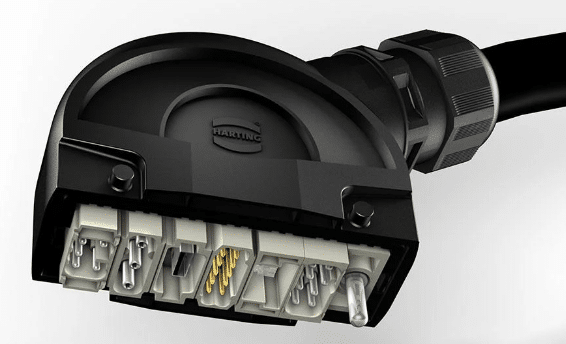
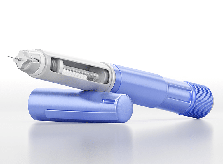
Autoinjector housings are produced in very high volumes and must meet demanding requirements for dimensional accuracy, cleanliness, and consistency. Rising global demand for MED-PEN injection devices, especially those used for weight management therapies, has put significant pressure on mold makers to improve cooling performance and increase productivity.
ZAHORANSKY Automation & Molds, a major supplier of high-precision medical tooling, partnered with AddUp to investigate whether conformal cooling enabled by metal additive manufacturing could shorten cooling times and enhance temperature stability inside the mold. The project focused on improving thermal behavior, raising output, and validating corrosion-resistant AM tool steels for high-volume medical applications.
From Cooling Limits to High-Speed Autoinjector Production: Unlocking Cycle-Time Gains with AM Cooling
MATERIAL
Printdur HCT (1.2083 / PM420)
INDUSTRY
Tooling and Mold Making
CHALLENGE
Reduce cooling time and stabilize temperature distribution in autoinjector housing molds to support rapidly growing MED-PEN demand. The goal was to evaluate whether additively manufactured conformal cooling channels could outperform conventional cooling strategies and enable faster, more reliable production at high volumes.
KEY BENEFITS
- More than 30 percent reduction in cycle time
- Uniform mold temperature without hotspots
- Longer tool life through balanced heat distribution
- Higher output and more reliable processing for large production runs
- Smaller mold space requirements enabling more economical machine use

Shortened Cycle Times

Higher Output

Smaller Space Requirements
The Customer
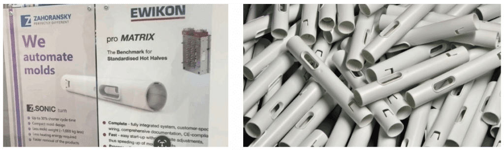
ZAHORANSKY is among the leading manufacturers in tool and mold making.
The company is known for its innovative, high-precision tooling systems. Their solutions emphasize repeatability, reliability, and the ability to operate within automated, compact production environments.
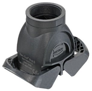
As demand for autoinjector housings grows into the millions, ZAHORANSKY has been evaluating new processing strategies that can improve cooling efficiency and reduce cycle time. Conformal cooling produced using L-PBF technology has shown particular potential for delivering these performance gains while remaining compatible with the Z.SONIC turn tooling concept and modern medical molding platforms such as the Netstal Elion 1200 MED.
The Challenge
Producing autoinjector housings requires precise molding of sensitive features and the ability to maintain consistent temperatures throughout each cycle. With MED-PEN consumption rising, production volume requirements are pushing mold systems to their limits. In addition to molding the plastic housings themselves, ZAHORANSKY must also support the precise assembly of sensitive medical components within highly automated systems, which increases the importance of stable thermal behavior and consistent part quality.
ZAHORANSKY needed to determine whether additively produced conformal cooling could support:
- Faster cooling inside compact tool dimensions
- Improved thermal uniformity and the elimination of hotspots
- Higher output for large production runs
- Lower scrap rates through more stable temperature control
- Compatibility with the Z.SONIC turn system that transfers part of the cooling phase outside the tool
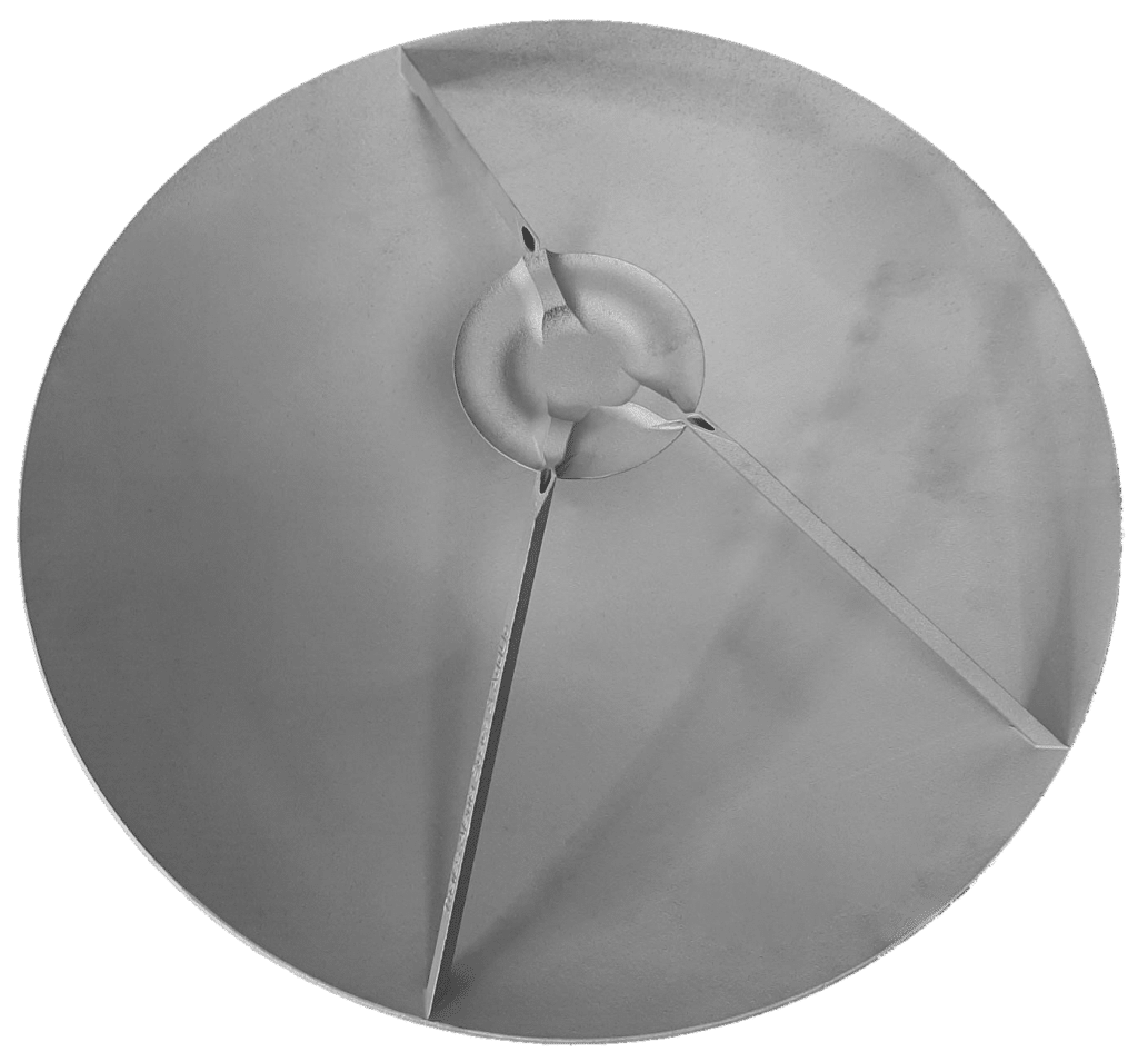
ZAHORANSKY’s Z.SONIC turn tooling concept uses a 180-degree rotation to transfer the molded part outside the cavity while the next injection cycle begins. This movement allows a significant portion of the remaining cooling time to take place outside the tool, reducing the in-mold cooling requirement and enabling faster cycle progression. In the current configuration, the system achieves an 8.5-second cycle time by combining internal cooling, external cooling, and continuous part rotation. To fully leverage this mechanism, ZAHORANSKY required even shorter internal cooling times, which became a key driver for exploring additive conformal cooling on the FormUp 350.

The Solution
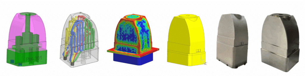
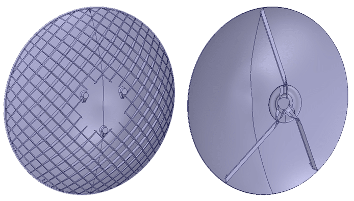
AddUp and ZAHORANSKY first carried out a simulation-based evaluation to determine the potential performance gains. These early studies confirmed that a conformal cooling concept could significantly reduce cooling time and improve thermal stability. Based on these results, a fully three-dimensional cooling design was developed, incorporating a four-path parallel cooling circuit to ensure balanced flow and consistent temperature behavior inside the tool.
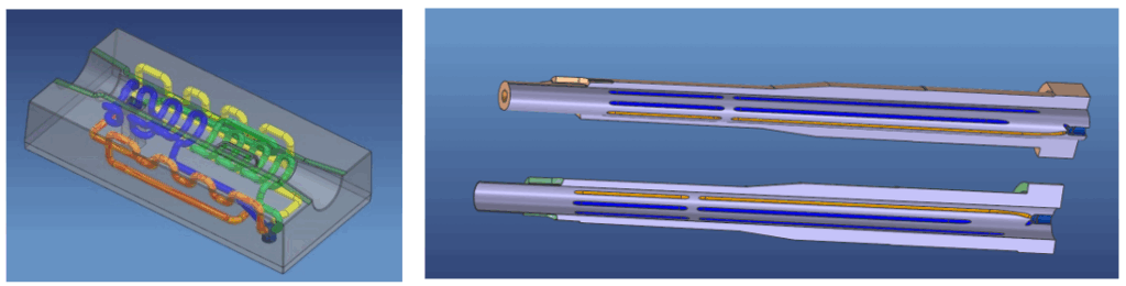
Because the cooling channels follow the exact contour of the cavity and core, heat can be removed precisely where it is generated. This leads to faster and more uniform cooling and supports stable, high-quality molding within a compact, automated production system.
This approach enables:
- Shorter cycle times
- Uniform temperature distribution throughout the insert
- Reduced distortion and more reliable dimensional control
- Stable processing during high-volume production
Conventional drilled or milled cooling channels cannot achieve such geometries and often require vacuum-brazed assemblies, which introduce limitations in thermal conductivity, increase the risk of leakage, and complicate repairs. Additive L-PBF manufacturing avoids these constraints by producing single-piece inserts with fully integrated freeform cooling channels.
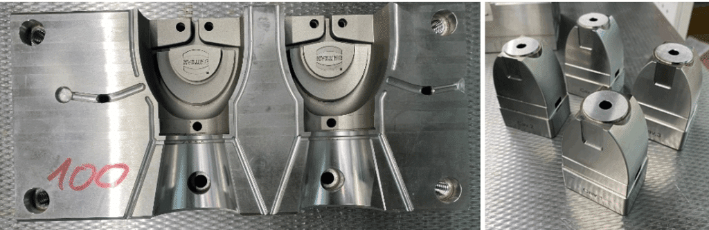
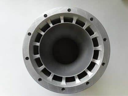
For this project, five AM cavity inserts and twelve AM cores were manufactured on the AddUp FormUp 350 using a four-laser configuration. Total production time included 12 days of net printing and 5 days for design and auxiliary preparation. The selected material was a corrosion-resistant tool steel based on 1.2083 / PM420, ideal for injection molding and suitable for high-gloss Class 1 surface finishes.

After printing, the build was depowdered, heat-treated, and wire-cut from the platform. Final machining was completed at ZAHORANSKY to achieve the required tolerances and surface quality.
The Results
The additively cooled inserts and cores delivered significant and measurable improvements in cooling performance and tool stability.
Key findings:
- Cycle time reduction greater than 30 percent
- Cooling time reduced to 9 seconds compared to more than 14 seconds previously
- Uniform mold temperature without hotspots
- Improved part quality and reduced scrap
- Longer tool life through balanced thermal behavior
- More reliable processing during large production runs
These results demonstrate that AM-based conformal cooling provides a clear performance advantage over traditional straight-line channels and supports stable, high-volume manufacturing of autoinjector housings within compact, automated production cells.