• Skip to primary navigation
  • Skip to main content
  • Skip to footer
AddUp

AddUp

  • Machines
    • Machines
      • PBF
        • FormUp 350
        • FormUp 350 Evolution
      • DED
        • Modulo 400
        • Magic 800
      • Software
        • AddUp Dashboards
      • Why AddUp
        • Customer Journey
        • Certifications
  • Service
    • Service
      • Consulting
      • Training
      • AddUp Academy
  • Industries
    • Industries
      • Medical
      • Tooling & Molding
      • Aerospace & Defense
      • Other
  • Applications
  • Resources
    • Resources
      • Guide to Metal 3D Printing
      • Blog
      • Videos
      • Events
      • Materials
      • Downloads
      • AddUp Academy
      • Customer Portal
  • Company
    • Company
      • News & Press
      • Partners
      • Careers
      • Company Locations
      • Supplier Portal
  • Contact
        • Search

  • EN
    • FR
    • DE

FormUp 350

October 2, 2023 by

See how AddUp and PrintSky develop a good rigidity/mass balance with a high technical and economic value for an aeronautical part.

The CEA (French Alternative Energies and Atomic Energy Commission) has joined forces with AddUp to create the Famergie platform to help energy sector manufacturers develop projects for the production of parts using metal additive manufacturing. The first project resulting from this partnership is a demonstrator of a methanation exchanger-reactor. This device converts CO2 into methane, which can be used as synthetic fuel. As the methanation reaction occurs at high temperatures and pressure, the design of the exchanger is crucial for the efficiency and control of the entire methane production. Read the case study about additive 3D printing of the aerospace support part using the FromUp 350® machine.

OBJECTIVE

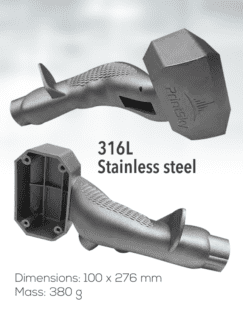
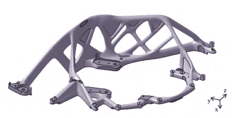
Print a lightweight metal 3D support part

RESULTS
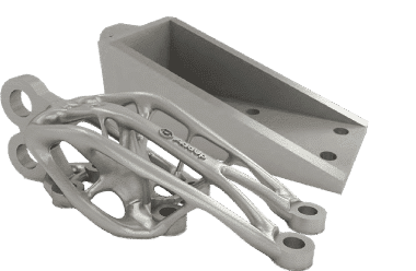
  • 40% mass savings compared to the maximum target of 600 g given
  • Compliance with the dimensions of the original part, for fastening and assembly.


Context

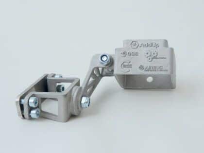
PrintSky is a joint venture between the AddUp group, an expert in metal additive manufacturing, and SOGECLAIR specialized in the integration of high-value-added solutions in the fields of aeronautics, space, civilian and military transport. The CEA (French Alternative Energies and Atomic Energy Commission) commissioned Printsky to redesign a typically machined support part using the possibilities offered by additive manufacturing to reduce its mass. This support must also precisely ensure its functionalities to hold the equipment it has to support and resist the stresses it is subjected to.

Implemented Means

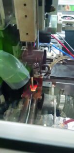
PrintSky was in charge of the design part of the project, developing its own experience and methodology to implement the characteristics of the metal part, in terms of mechanics and manufacturability. The production was then entrusted to AddUp experts who 3D printed the aerospace part using their FormUp350® machine.

Advantages of 3D Metal Printing

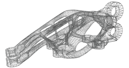
After topological optimization, additive manufacturing makes it possible to develop complex shapes, improve performance and reduce the volume of a metal part. It also allows the manufacture of very robust parts. Indeed, the material is added only where necessary, either to support forces or to ensure functionality such as fastening, support surface, or other. A good rigidity/mass balance with a high technical and economical value for an aeronautical part.

Results

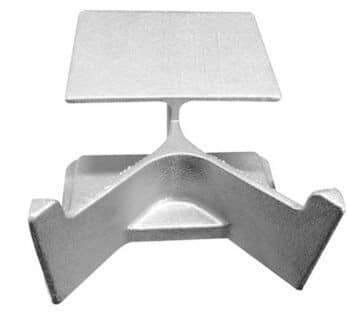
The optimized support fulfills the same functions as the original support, but with a significant mass reduction, impossible to achieve with conventional technologies.

The use of fine powder allowed to obtain a good surface finish and finally the part was manufactured without support, which allows a significant time-saving in post-processing.

The AddUp Advantage

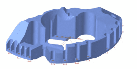
The mastering by AddUp of the material characteristics obtained on FormUp350® and of the additive manufacturing simulation tools has allowed us to anticipate the thermo-mechanical distortions and to obtain compliant parts after only one iteration.

October 2, 2023 by

An additively manufactured camera support, designed to withstand acceleration and vibration during launch to space and to hold a camera and its lens in position during the production phases of a metal 3D printer.

“Metal3D“ project objective is to characterize the mechanical properties of a material shaped in microgravity. To carry out this experiment, two batches of test specimens are being produced by the same printer design. While the first batch will be produced in Toulouse in terrestrial gravity, the second will be built in space, more precisely in the Columbus module of the ISS (International Space Station), in microgravity.

GOAL

Position and hold a camera and its lens in position during the flight and manufacturing phases

APPLICATION

3 positioning axes for precise camera field adjustment. Designed to withstand acceleration and vibration during launch

CONTEXT:

“METAL3D“ PROJECT

MASS:

70 g


Mission

“Metal3D“ is a mission commissioned by ESA (European Space Agency) as a technology demonstrator. Its objective is to characterize the mechanical properties of a material shaped in microgravity. To carry out this experiment, two batches of test specimens are being produced by the same printer design. While the first batch will be produced in Toulouse in terrestrial gravity, the second will be built in space, more precisely in the Columbus module of the ISS (International Space Station), in microgravity. To produce these two prints, we have designed and manufactured two identical copies of a metal 3D printing machine capable of operating in both environments. The printer we have designed for this mission will therefore be the first to print metal parts in space.

Process

In the absence of gravity, the majority of current additive manufacturing processes are no longer usable. To make microgravity manufacturing possible, we choose to exploit the forces induced by surface tension. We use a laser as the energy source and steel wire as the raw material. The laser heats the substrate to create a liquid bath. In this liquid bath, we immerse the steel wire. By pushing the wire into the liquid bath, the latter also liquefies and increases the volume of the fusion bath. We then move the laser and therefore the liquid bath to the surface of the substrate while unwinding the wire in this bath so as to create a bead once the liquid bath has solidified. A layer is made up of one or more beads depending on the geometry of the part to be produced. Once the layer is finished, the process starts again using the previous layer as a substrate. In this way, layer by layer, a volumetric part is created.

For the process, we use a 316L wire. The laser and wire are fixed in the machine frame, it is the tabletop that is made mobile through 3 linear axes and 1 rotary axis. The machine is operated under nitrogen in order to limit the oxidation of the material and prevent the risk of combustion. As the access to nitrogen is limited in the ISS, this atmosphere is recycled throughout the manufacturing process by filtration and cooling.

Partners

The mission is being piloted by the Airbus Defense & Space teams. Cranfield University provides the laser, the optical chain, and the wire supply system to the system. Hightech provides the machine enclosure, which provides a sealed and cooling system, and the interfaces between the machine and the rack to which it is connected. Airbus, in addition to piloting the project, is managing the electronic and safety aspects of the machine.

On the mechanical side, AddUp is in charge of the internal structure and the mobile part of the machine. AddUp also manages the control board and the sensors that monitor the process. On the software side, AddUp has developed the machine’s PLC. This software has several functions, it allows communication with the ground by sending different types of data (measurements, photos, reports, etc.) from the machine and by executing the commands it receives.

October 2, 2023 by

The freedom of design linked to metal 3D printing allows the production of customized handles, of different dimensions, without tooling, thus limiting the costs and manufacturing lead times of the parts.

The freedom of design linked to metal additive manufacturing allows the production of customized handles, of different dimensions, for right or left-handed people, without tooling, thus limiting the costs and time of manufacturing the parts. Read the case study about AddUp and PrintSky partnership for the 3D printing of a complex ergonomic controller.

CHALLENGE

3D printing of a complex ergonomic controller

RESULTS

Thanks to the use of a fine powder and a system of spreading the powder by a scraper, the part manufactured on the FormUp 350® machine has a low surface roughness, allowing the handle to be used immediately, without reworking.

Context

The Joystick, a multi-axis handle is specially designed for the piloting of demanding vehicles (turrets, drones, lifting equipment, etc.) combining excellent ergonomics with a wide range of applications.

For this project, AddUp partnered with PrintSky who designed the flight stick to ensure the mechanical and manufacturability characteristics of the metal part would be met. The part has been designed to allow for the dimensions to be updated to suit the shape and grip of each driver, as well as the position and type of button for each application.

The part was optimized for the Powder Bed Fusion (L-PBF*) process, reducing the wall thickness of the handle down to just 1 mm, compared to 3 mm for castings. The part was then printed on the FormUp® 350 PBF machine.

The Advantages of Additive Manufacturing

PBF technology is particularly suitable for applications that require customization, function integration, and weight savings while maintaining high mechanical strength.

This Joystick was made of 316L stainless steel and is remarkably strong and perfectly suited for off-road vehicles and machines. Its special grip makes it easy for the rider to grasp the handle. This part is a one-piece construction with modular inserts to provide design flexibility and ease of installation.

October 2, 2023 by

How reverse engineering process and metal 3D printing allow to produce an identical and durable strategic part for a boat.

CHALLENGE

Reproduce an identical part that is no longer in stock

SOLUTION

Reverse engineer the part (from a manual drawing to a digital CAD file) and additively manufacture it using the FormUp 350® Powder Bed Fusion machine from AddUp.

KEY BENEFITS
  • Tolerances: +-0.4mm, depending on demand
  • Similar mechanical characteristics, better durability
  • Overall balance of the printed part maintained
icon addup
Custom Shape
icon addup
Lead Time
icon addup
Integrated Features
icon addup
Performance

Context

Drawing of the original part

In 2018, the Ministry of the Armed Forces created the Defense Innovation Agency to promote innovation in the armed forces, with the priority to disseminate the latest technologies quickly. Under this driving force, the various services have all set up cells to boost innovation adapted to each profession. The Service de Soutien à la Flotte (Fleet Support Service), or SSF, in charge of piloting innovations for the maintenance of the French Navy’s fleet ships set up a similar initiative in 2020.

One of the French Navy’s challenges is to determine how to produce an out-of-stock part. To meet this demand, the Navy, the SSF, and the Service Logistique de la Marine (SLM, or Navy Logistics Service) needed a solid industrial group that has mastered the entire value chain. This is why the Navy turned to AddUp, a manufacturer of machines and parts, and an expert in metal 3D printing.

For the first test, the Navy chose an oil scraper for the propeller shaft line bearings of a Frigate, a part that plays an important role in the continuous lubrication of the bearings. This part is so essential for the operation of the Frigate and has the advantage of not presenting any critical mechanical stress for the safety of the ship, which authorizes such an experimental production attempt. Repeated contact with the splash plate and the bearing housing can lead to premature wear. This, along with the low stock of spare parts was a complementary and motivating factor for the choice of this part.

Additive Manufacturing Advantages

An identical part was 3D printed in aluminum. The original part was cast on a foundry layer and needed machining, which increased the production time. The new part was produced in one go, in one block, thus saving a significant amount of time. The use of a FormUp® 350 coupled with a fine powder coating roller has made it possible to produce a part with geometric precision and with a very good surface finish (superior to foundry) which has minimized the post-processing stages. AddUp has mastered the entire production chain: design, additive manufacturing, post-processing, and quality control.

“The experimentation of metal additive manufacturing with AddUp went well. The endurance tests on the ship were positive and AddUp is now referenced as a supplier of scrapers in the same way as other suppliers who produce this material using conventional techniques. The cost analysis shows that this production method is competitive. The delivery time is similar or even shorter. The collaboration was perfect and allows us to envisage other cases of application.” Jean-Marc QUENEZ French Navy Fleet Support Service Innovation

October 2, 2023 by

See how this 3D printed inductor has met all quality specifications, and its industrial performance has surpassed initial expectations.

An induction heating coil is a production tool that allows performing a local heat treatment on metallic parts; in this case, it is used to braze contact tips on copper or brass parts, assembled into circuit breakers and contactors. Schneider Electric’s Plant 4.0 in Le Vaudreuil, Normandy (France), is a showcase for the new industrial revolution. Identified as one of the most developed factories in the world, it uses the latest technological advances in IloT, mobility, sensing, cloud, analytics, and cyber security. This plant manufactures 40,000 contactors per day. Read the case study about the additively manufactured inductor.

INDUSTRY

Energy

CHALLENGE

3D print a “Plug & play“ inductor with short lead time

KEY BENEFITS
  • Part with complex geometries
  • Improve metal part performance
  • Reduction of production time
icon addup
Creative Shape
icon addup
Lead Time
icon addup
Weight
icon addup
Performance

Challenges

Schneider Electric redesigned an inductor to maximize its technical and industrial performance. This new inductor was designed to reach the right temperature at the solder without damaging the pellet or the support, all while reaching the expected cycle time. This new inductor was impossible to manufacture using conventional processes, but additive manufacturing enabled it to overcome these manufacturing constraints. Schneider Electric called on AddUp to provide ease of production for this complex part and short lead times.

Schneider Electric was in search of a new inductor that could meet the following requirements:

  • Be a good conductor of current (it is the current flowing in the inductor that induces the electromagnetic field responsible for the heating)
  • Watertight (water flows through the inductor to cool it)
  • Be robust and durable (dimensional stability, service life, ability to change tools, etc.).

Solution

Using the FormUp 350, AddUp could provide an inductor based on Schneider Electric’s needs and in a fraction of the time, it would have taken to conventionally manufacture the previous version of an inductor.

Schneider Electric integrated this inductor into their production line to perform the following tests:

  • Leak test
  • Water flow measurement
  • Power up and soldering parts while analyzing hot spots with an infrared camera
  • Cycle time measurement

Following these tests, Schneider then checked the manufactured parts. In particular, the quality of the solder joints was inspected visually as well as via a pull-off test, ultrasonic inspection, micrographic section, and hardness sampling.

Results

The final result was an additively manufactured inductor successfully integrated into the Schneider Electric production line. The inductor has met all quality specifications, and its industrial performance has surpassed initial expectations.

“Additive manufacturing has enabled us to obtain a disruptive, innovative, high-performance design and a “plug-&-play” inductor. The inductor supplied by AddUp was easily integrated into our system directly, without any rework on the part. The production time was reduced, which offers a very interesting reactivity, especially for parts with complex geometry. Finally, the industrial performance exceeded our initial expectations, and the inductor has not been changed in the past four months. This is significant because a conventionally manufactured inductor is typically changed every six months. “

~ Guillaume Fribourg, Materials and Processes Expert, Additive Manufacturing Project Manager, Schneider Electric
The copper inductor installed and tested

September 29, 2023 by

INDUSTRY

Aerospace

CHALLENGE

Reducing the mass and lead time while optimizing
an Aircraft Floor Bracket

KEY BENEFITS
  • 61% mass reduction of the part
  • Part printed without any supports
  • Industry leading surface finish
icon addup
Reduced Lead Time
icon addup
No Support
icon addup
Weight Reduction

This proof of concept demonstrated by Add Up showcases the value of using Additive Manufacturing (AM) for aeronautics by applying topological optimization to an aircraft floor bracket.

History

An aircraft floor bracket secures the cabin floor to the fuselage and is present in large quantities in all aircraft. AddUp developed this proof of concept demonstrator to illustrate the value of using Additive Manufacturing for aeronautics by carrying out a topological optimization study with no supports. This part traditionally weighs around 3 kg and is typically machined from a 12 kg metal block.

Challenges

The weight of an aircraft poses various challenges, including structural integrity, fuel efficiency, payload capacity, and performance during takeoff and landing. Excessive weight can strain the aircraft’s structure, increase fuel consumption, limit payload capacity, and require longer runways.

Safety considerations, such as balance and stability, are crucial, and the cost and economics of weight must also be considered. To address these challenges, aircraft designers and operators focus on using lightweight materials, efficient designs, and operational practices that strike a balance between weight reduction, performance, and safety.

In most metal 3D printing machines, supports must be added to the part to produce surfaces with an inclination of less than 45° from the horizontal. These supports represent a significant cost and contribute to the time of part delivery.

SOLUTIONS

Topology optimization, the mathematical method that optimizes material within a given space with the goal of maximizing performance, was utilized to remove significant amounts of material.

First, a CAD model was created, incorporating the desired shape and the stress constraints the part needs to withstand.

Next, topological optimization algorithms evaluated the stress distribution throughout the part and systematically removed excess material from low-stress regions while reinforcing high-stress areas.

This resulted in a lightweight design that maintains structural integrity under anticipated loads. The part was then printed on the FormUp 350 powder bed fusion machine, using a fine powder and roller combo to reduce the need for supports. This combination also provided a smooth and uniform surface finish, which plays a critical role in the fatigue behavior LPBF parts and reduces the need for post-processing.

The Results

By utilizing the fine powder and roller recoater combination found only on the FormUp 350, there were no support structures required; overhangs can go as low as 30° or even 15°. By removing the need for support structures, 250 g of raw material was saved. This reduced the build time by 3 hours and saved another 30 minutes for support removal. This also lowers the overall total lead time, an important metric in the Aerospace industry.

Build Time on the FormUp 350 (at 50 μm)
11.50 Hours

Weight Reduction
From 3 Kg down to 1.17 Kg
A 61% weight reduction!

Raw Material Savings
10.83kg

Saved Time
3+ hours

  • « Go to Previous Page
  • Page 1
  • Page 2
  • Page 3
  • Go to Next Page »
AddUp SAS

13-33 Rue Verte
ZI de Ladoux, 63118 Cébazat
France

+33 (0)4 73 15 25 00
AddUp Inc

5101 Creek Rd,
Cincinnati, OH 45242
USA

+1 (513) 745-4510
AddUp GmbH

Campus-Boulevard 30
52074 Aachen
Germany

+49 241 4759 8581

Footer

  • Machines
    • PBF
      • FormUp 350
      • FormUp 350 Evolution
    • DED
      • Modulo 400
      • Magic 800
    • Software
      • AddUp Dashboards
    • Why AddUp
      • Customer Journey
      • Certifications
  • Service
    • Training
    • AddUp Academy
  • Industries
    • Medical
    • Aerospace & Defense
    • Tooling & Molding
    • Other Industries
  • Applications
  • Resources
    • Guide to Metal 3D Printing
    • Blog
    • Videos
    • Events
    • Materials
    • Downloads
    • AddUp Academy
    • Customer Portal
  • Company
    • News & Press
    • Partners
    • Careers
    • Supplier Portal
  • Contact

© 2025 AddUp. All Rights Reserved. Privacy Policy| Terms of Use| Legal Notice

Ask an addup expert